
Technical case study #2 - Structural Drawing & Calculation Sheet Walkthrough

In the previous article, we explained the project setup and design methodology behind our generative design copilot.
In this article, Genia Co-founder Robin Li will give us a walkthrough of one of the recommended design options that we present to the client. Our deliverables consist of a structural drawing file in CAD format, as well as a calculation sheet showing code compliance checks and structural performance analyses.
User Interface
If you haven't seen our product demo before, here is a short video capturing the user interaction of creating a project in our Generative Design copilot.
Users can specify the location and upload the architectural drawings in CAD format, and our systems can run the design generation and provide the generated results usually in just a minute or two.
Each of the generated design options will contain a structural drawing file in CAD format, as well as a detailed calculation sheet in PDF. Let's walk through one of the generated options for the sample project in Medina, WA, shall we?
Structural Drawing
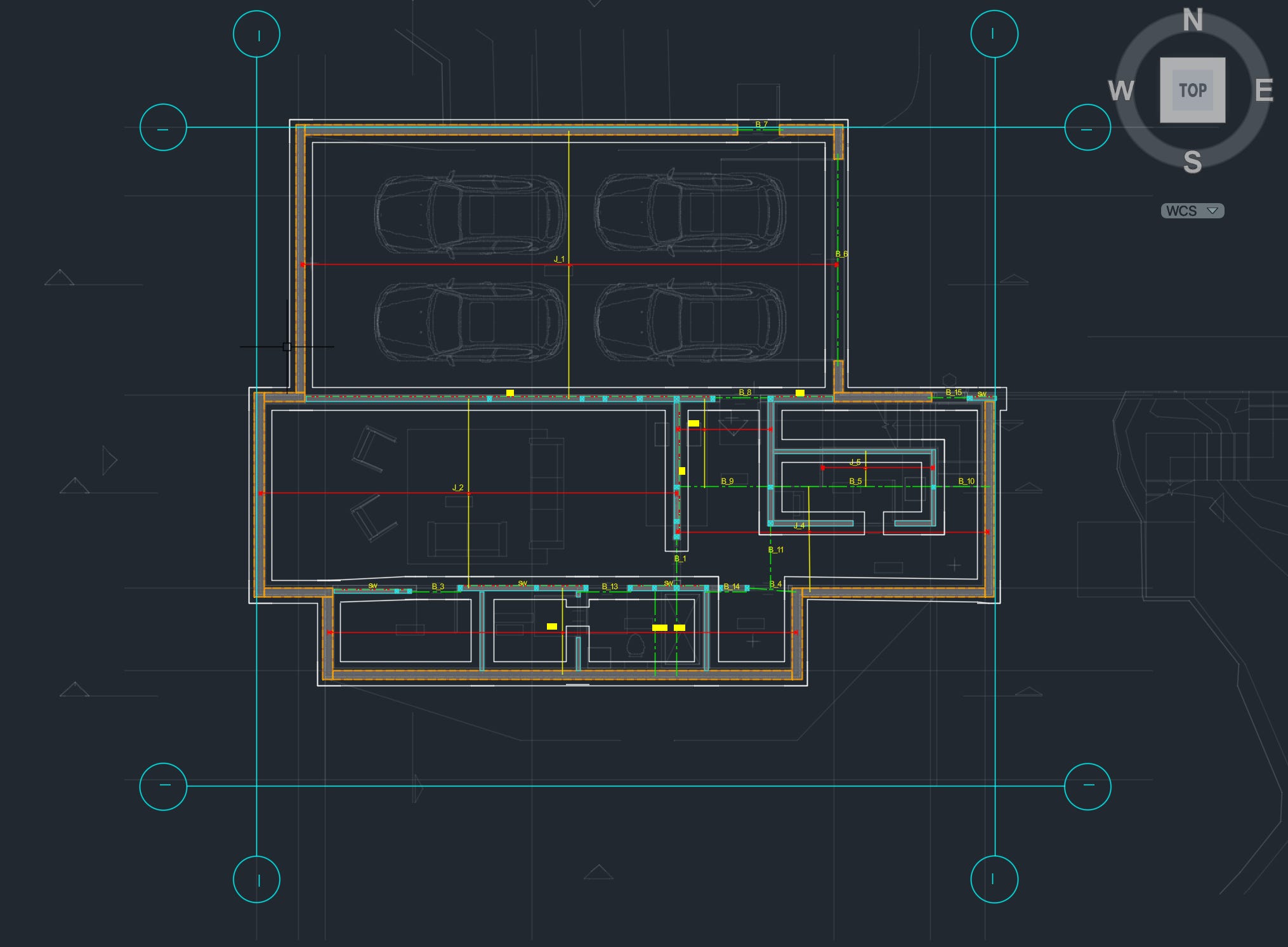
Here is the structural drawing in CAD that we generate for the sample project.
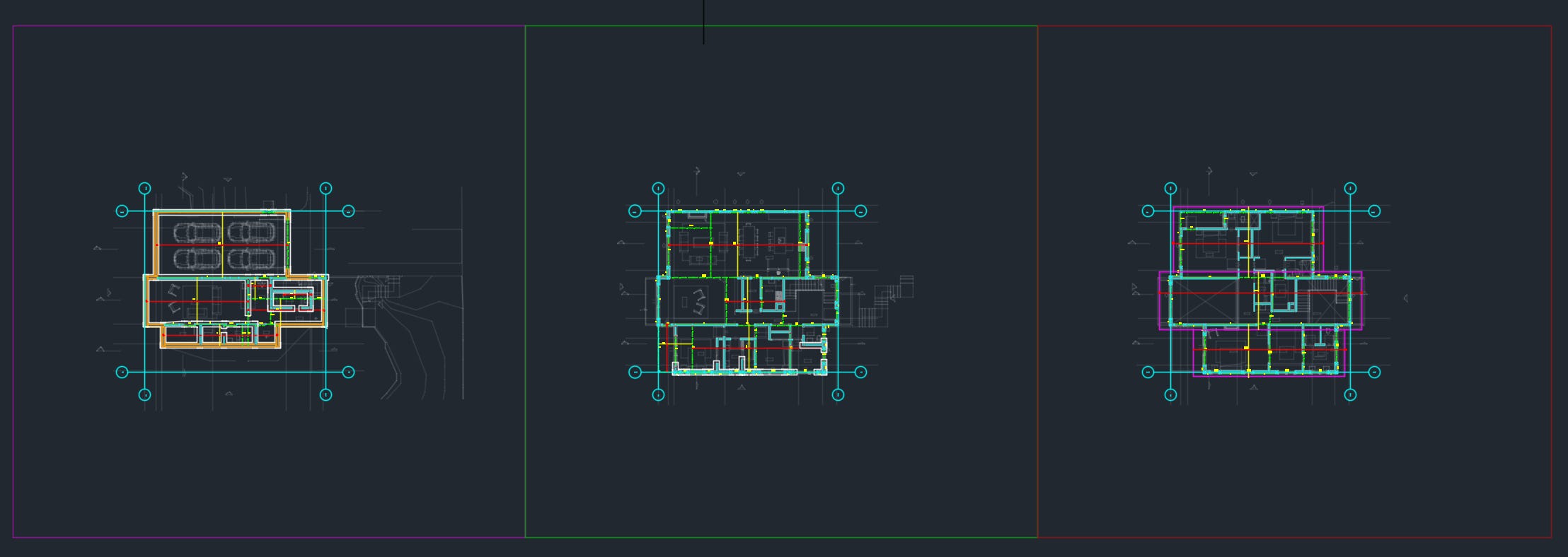
In the file, we place the structural plan of the three floors side by side, along with a legend block on the left. For all floors, the new structural design is placed directly on top of the original architectural drawing, whose elements are dimmed with a light gray color. Each floor is surrounded by a set of grid lines in cyan blue color to help with placement anchoring across floors.
Level 2
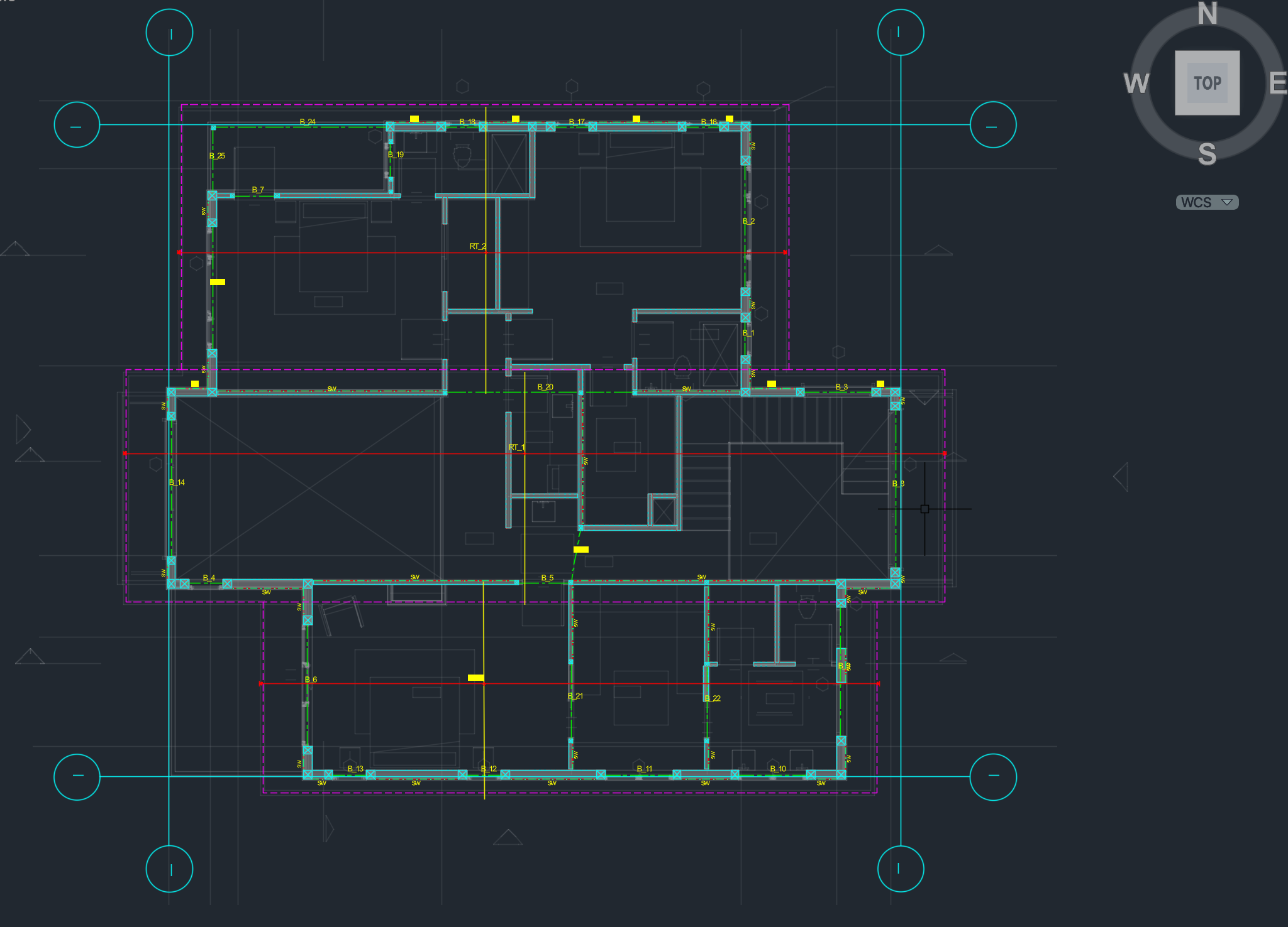
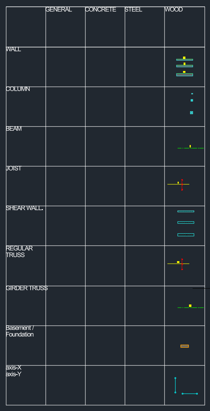
On Level 2, the three segments of the roof are first supported by three rafters. We then add beams, shear walls and posts to form the structural systems that would resist both the gravity and lateral systems. All beams, rafters and shear walls are annotated and numbered accordingly and in the same fashion as in the calculation sheet.
Level 1
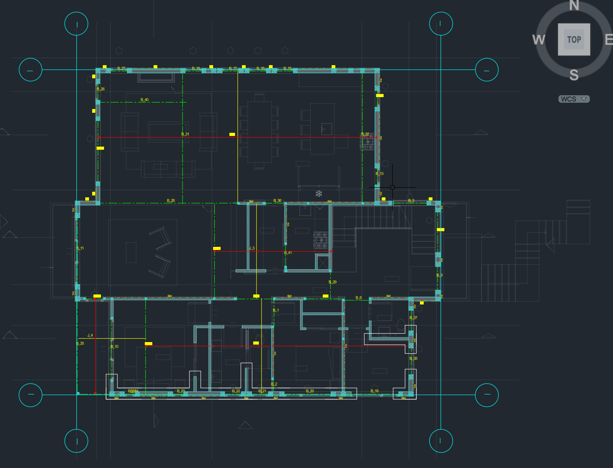
For Level 1, joists are used to support the top floor. Opening areas like the living room and stairs are left uncovered. Joists are separated and supported by walls and beams. Extra beams are placed to support the gravity loading passed down from the top floor, for instance from posts, as well as forming the lateral system with shear walls given this property is sitting in a seismic dominant area.
Basement
For the Basement, the exterior walls form the shear wall system for lateral stability. Joists and beams are placed to support the above floors. A concrete strip footing is designed as the foundation system. (Note that in this sample project we didn't receive the geo-tech report at design time, so we had to make some basic assumptions about the soil condition.)
Calculation Sheet
The Calculation Sheet can be found here.
In the video below, Robin will walk you through each section of the calculation sheet and give you a high-level summary of what you can expect for every design option that we generate.
Now that we've had a high-level overview of the design methodology and outputs, in the next article of the series we will dive deep into the design details of the lateral system for the building. This would cover how we analyze force requirements from wind and seismic loads and how we translate these requirements into shear wall details.
About the Authors

Robin Li is the Co-founder and COO of Genia and now leads product management. After graduating from University of British Columbia, Robin started off his career at Arup as a certified structural engineer, where he designed structures for a high-rise casino hotel in Macaw. Later, he returned to Canada and designed 100+ low-rise and mid-rise structures, including high-end custom homes in timber. You can find Robin on Linkedin or email him at robin@genia.design.
Still waiting for demo and access! :)