
Technical case study #3 - Lateral system design


In the previous articles, we have introduced the sample project and walked you through our deliverables, which include structural drawings in AutoCAD format and calculation sheets in PDF. In the next two posts, we will walk you through the detailed design sections, checking our generated design against building codes in the same fashion as a PE or SE would do. We start off discussing our lateral system design.
A. Seismic Load
A1. Methodology
For seismic design, we follow the Equivalent Lateral Force (ELF) procedure per ASCE 7-16 §12.8. The amount of seismic base shear is on the basis of approximate period of the building, site specific ground acceleration and response spectrum curve, site class of the site and type of building system used to resist the lateral forces. This type of analysis should only be used when the building is symmetric, torsion is minimal, no vertical or horizontal irregularities and no discontinuities in the system and where the primary mode of the structure governs the structural dynamics. This means that ELF analysis leads to fairly accurate results for short and very symmetric and regular buildings, which describe this sample project.
A2. Base Shear
According to ASCE 7-16 §12.8.1, the seismic base shear, V, in a given direction can be calculated using ASCE 7-16 Eq. 12.8-2:
where Cs is the seismic response coefficient and W is the effective seismic weight.
The seismic response coefficient can be calculated using ASCE 7-16 Eq. 11.4-3:
where SDS is the design spectral response acceleration parameter, R is the response modification factor, and Ie is the Importance Factor.
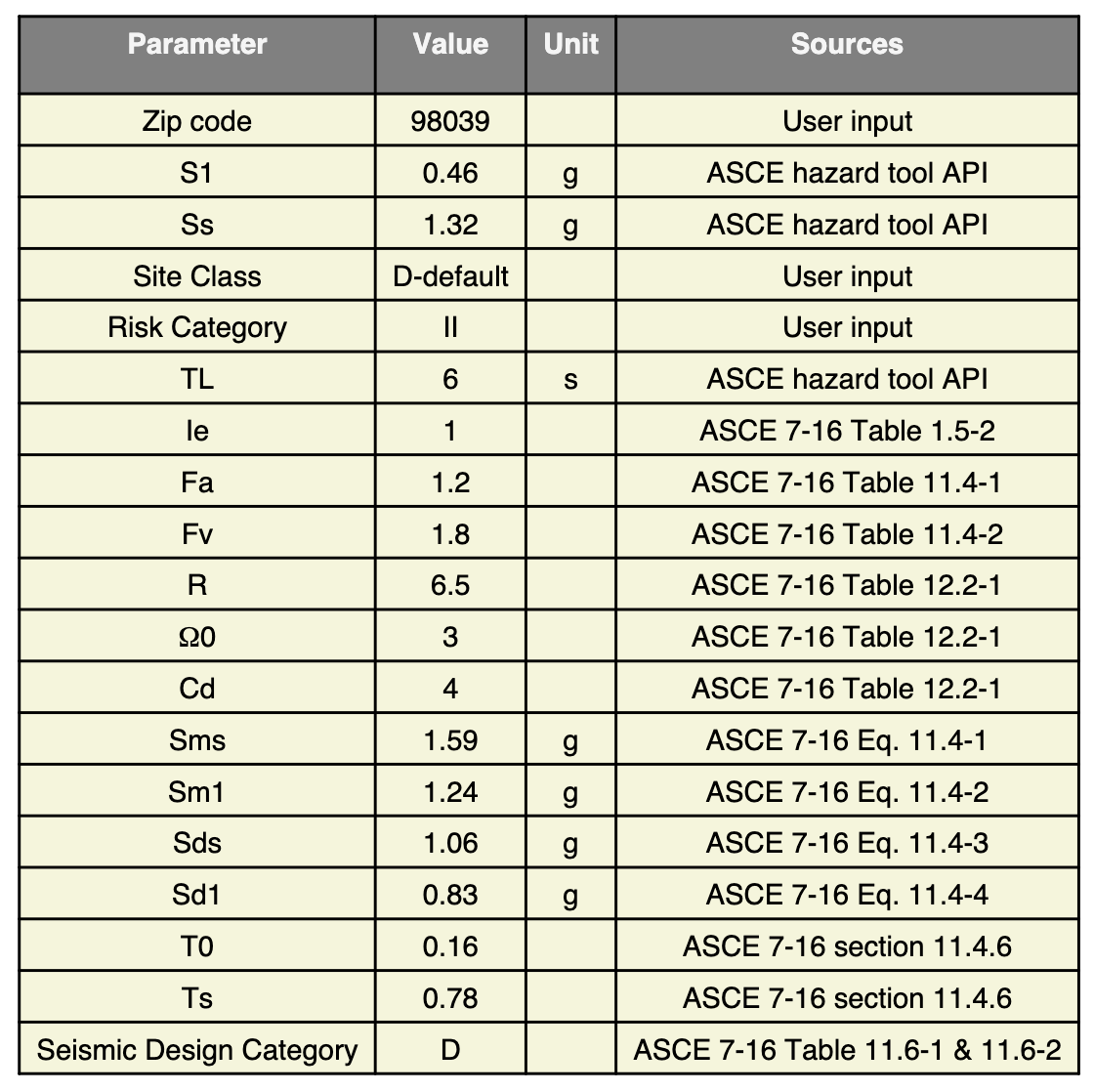
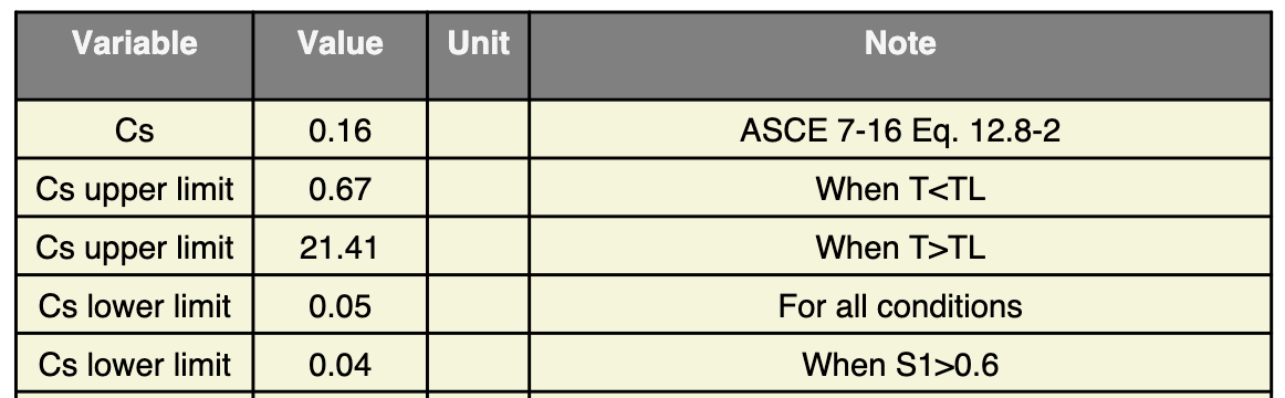
To calculate these values, we include the relevant parameter inputs based on the property location and specifications in this following table on page 9 in the Calculation Sheet and derive the value of Cs. We also check the upper and lower limits of Cs to make sure our calculated value falls within the applicable range.
We also calculate the effective seismic weight W for each floor and the entire building:
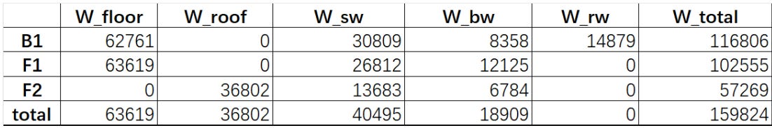
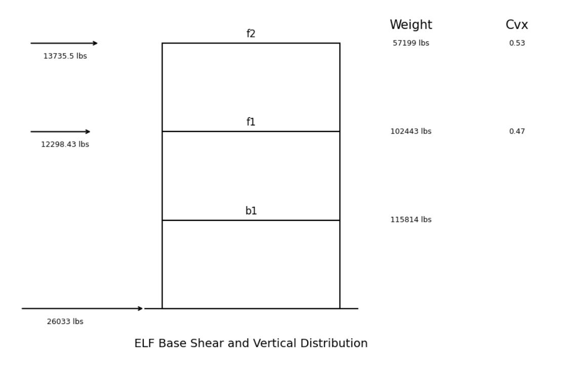
With the above values, we are able to calculate the base shear V = 26033.93 lbs.
A3. Vertical Distribution
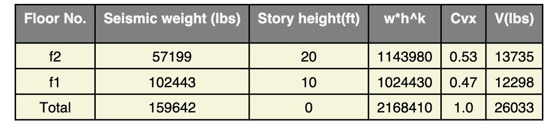
Now that we have derived the base shear, we then need to distribute it to each floor following ASCE 7-16 Eq. 12.8-11 and Eq. 12.8-12
and
Here are the results as shown on page 10 in our calculation sheet:
B. Wind Load
B1. Methodology
Although the project is located in a seismic-dominant region, we still run structural analysis on wind for completeness. To design the main wind force resisting system (MWFRS) for the building, we follow the the Directional Procedure for Buildings of All Heights as detailed in ASCE 7-16 §27.
Under the Directional Procedure, the process to calculate the wind load involves:
Determine the basic wind speed, V.
Determine site factors Kz and Kzt :
Velocity pressure exposure coefficient, Kz (ASCE 7-16 §26.10.1) based on the project's exposure classification and reference height above ground
Topographic factor, Kzt (ASCE 7-16 §26.8) based on the distance to hills and escarpments. We set this value to be 1 given the project is not built near a hill.
The ground elevation factor, Ke is set to be 1.
Calculate the velocity pressure, qz (ASCE 7-16 Eq 26.10-1)
Determine the internal pressure coefficient, GCpi (ASCE 7-16 Table 26.13-1) based on the enclosure classification.
Calculate the design wind pressures, p.
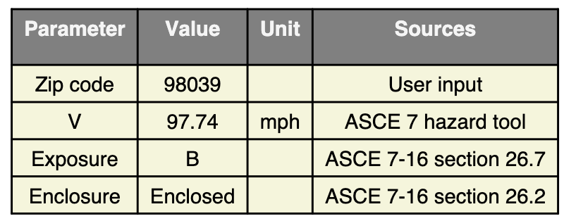
B2. Basic Wind Speed
As for the sample project, we obtain the following site parameters following the zip code of the location, assuming the project has exposure category B and is enclosed. The basic wind speed for this location is 97.74 mph based on the ASCE 7 Hazard Tool.
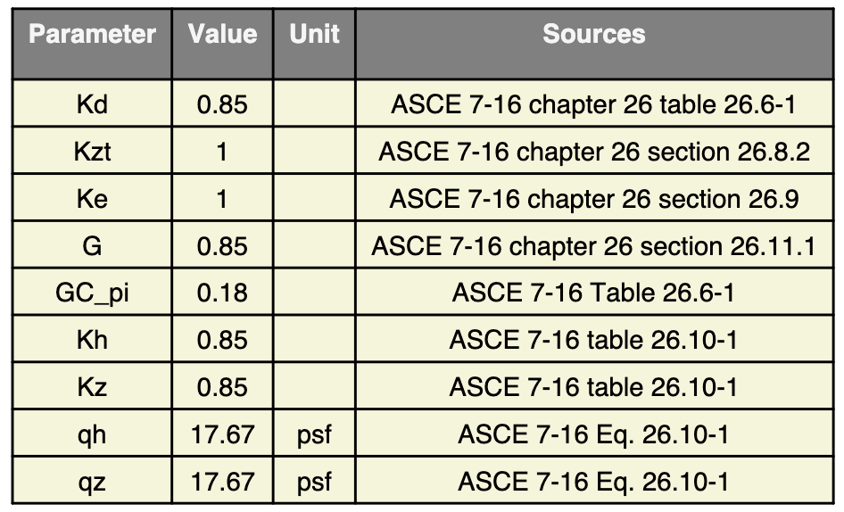
B3. Site Factors, Velocity Pressure, Internal Pressure Coefficient
For this project, below are the calculation results shown on page 12 of Calculation Sheet, including Kz, Kzt, qz and GCpi .
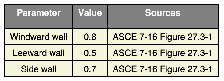
B4. Wind Pressure
To work out the wind pressure, we follow ASCE 7-16 Fig 27.3-1 and obtain the following values as shown in Calculation Sheet page 12.
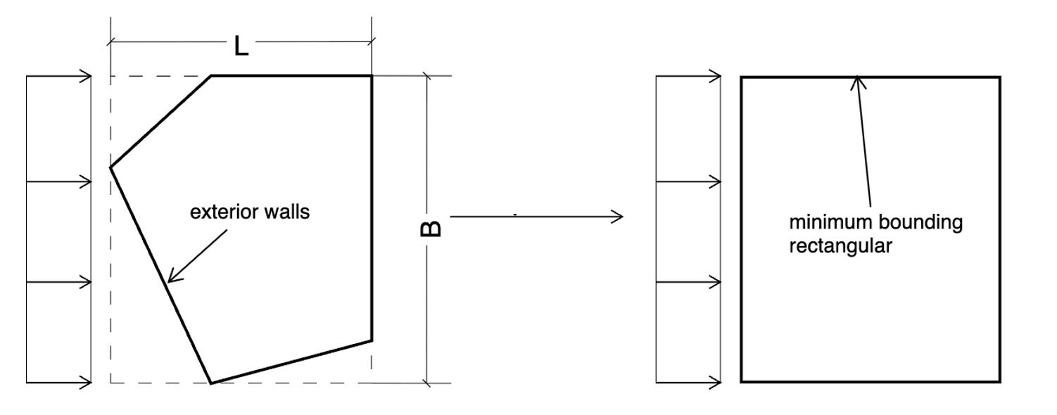
For wind pressure calculation, we simplify the building contour, often in complex shapes, to its minimum bounding box and consider the wind pressure applied to the bounding box instead. We believe doing so will not introduce errors as long as the building contour is convex and enclosed, because the x and y components from different sides will add up in effectively a rectangular shape. This assumption should hold true for most of the low-rise and mid-rise residential projects.
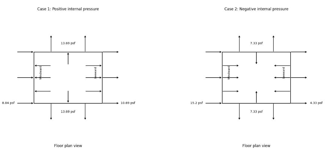
In the current version, we only consider Case 1: Full design wind pressure acting on the projected area perpendicular to each principal axis of the structure, considered separately along each principal axis, as mentioned in ASCE 7-16 Fig 27.3-18. Another limitation is that we do not consider torsion effect in the current version, which should not be a problem for wood frames given its nature of flexible diaphragm.
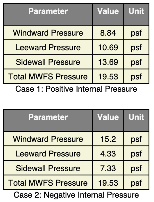
We therefore arrive at the following wind pressure requirements, as shown on page 12 in Calculation Sheet:
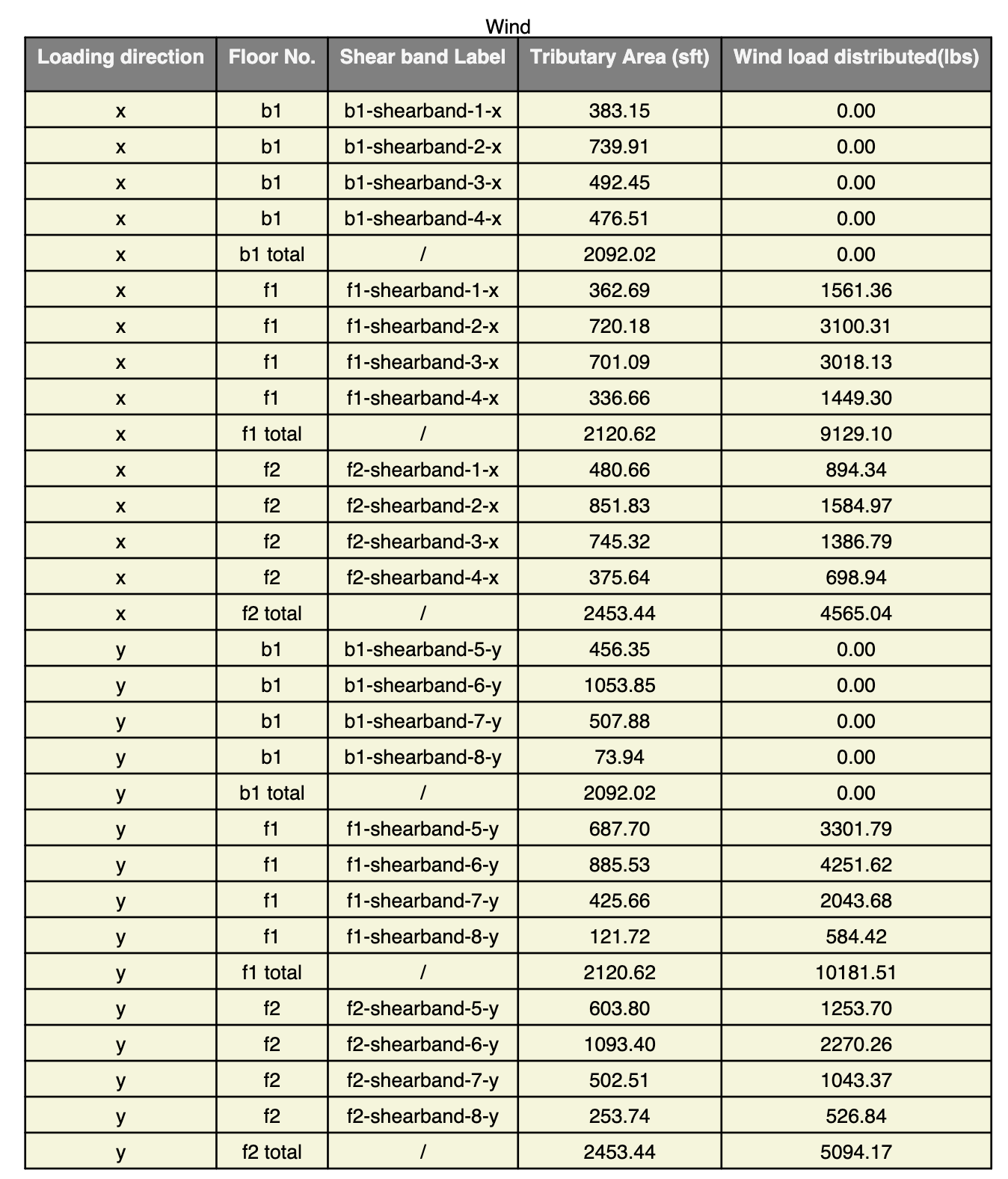
B5. Wind Load Distribution
Based on the above wind pressure, we further distribute wind load in x and y directions.
In x direction,
Roof wind load = qh × 0.5h × Broof
Floor wind load of the i-th floor = qh × 0.5h × (Bi + Bi+1)
Similarly, in y direction,
Roof wind load = qh × 0.5h × Lroof
Floor wind load of the i-th floor = qh × 0.5h × (Li + Li+1)
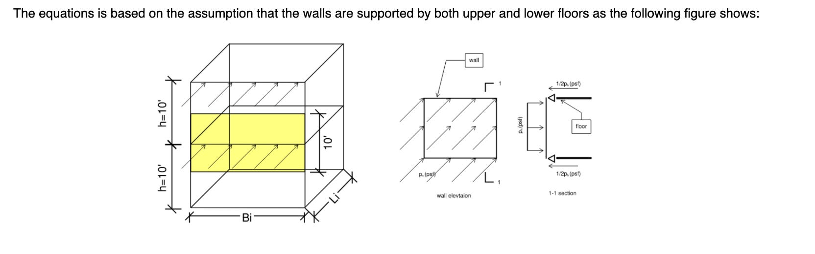
This explains how we arrive at the load distribution in Calculation Sheet on page 13.
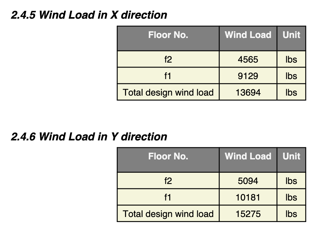
Note that the Basement is fully under the ground, so there is no wind pressure applied.
C. Lateral System Design
In the above sections, we outline the environmental loading factors based on the location and geometry of the building, which forms the basis of lateral force demands. Based on this information, our generative engine has suggested a layout of relevant structural component validated by our structural analysis engine. In this section, we will walk you through how this layout has been designed by AI, and how we validate the layout in structural analysis and specify material details.
C1. Design Assumptions
For the Lateral Force Resisting System (LFRS), our design uses shear walls, and we will be rolling our support for moment frames next month.
All exterior walls are considered as shear walls automatically.
As we mostly work with wood frames, we also follow the flexible diaphragm assumption for lateral calculations. We also do not consider accidental torsion in our calculations consistent with the flexible diaphragm assumption. We will begin support rigid diaphragms in the next release.
We also assume there is no vertical and horizontal irregularity for the property.
When the walls do not along across floors, we can support offsets up to 10 ft (3m) and passes along the lateral forces to adjacent shear bands in upper or lower floors.
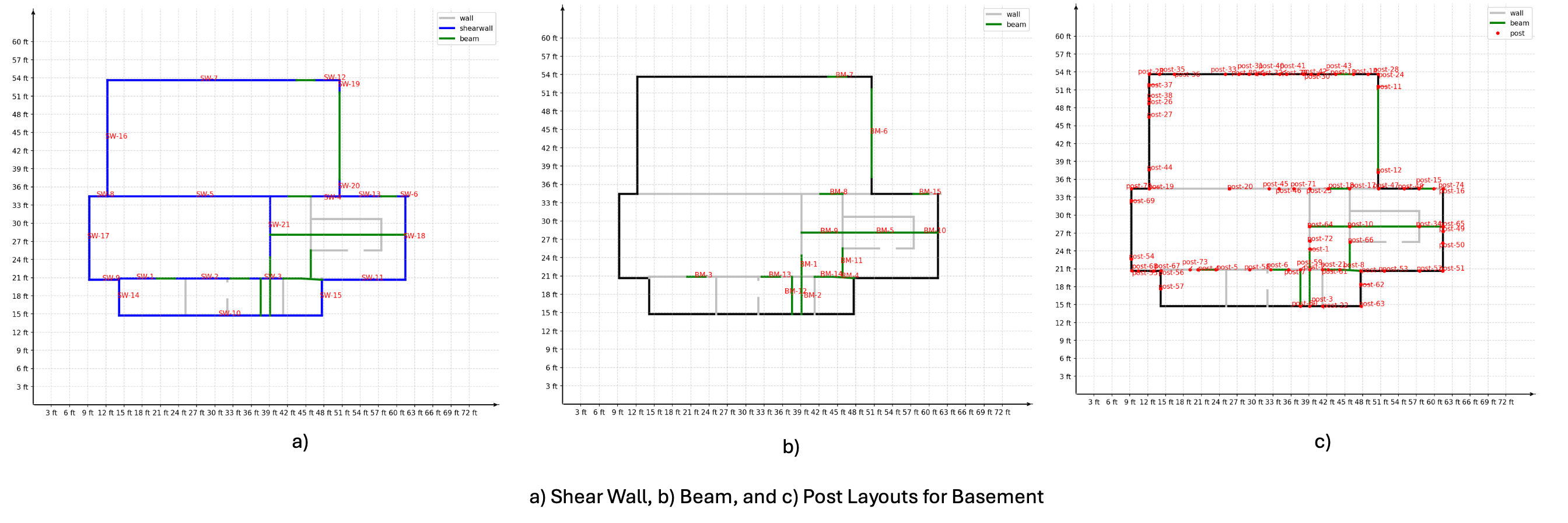
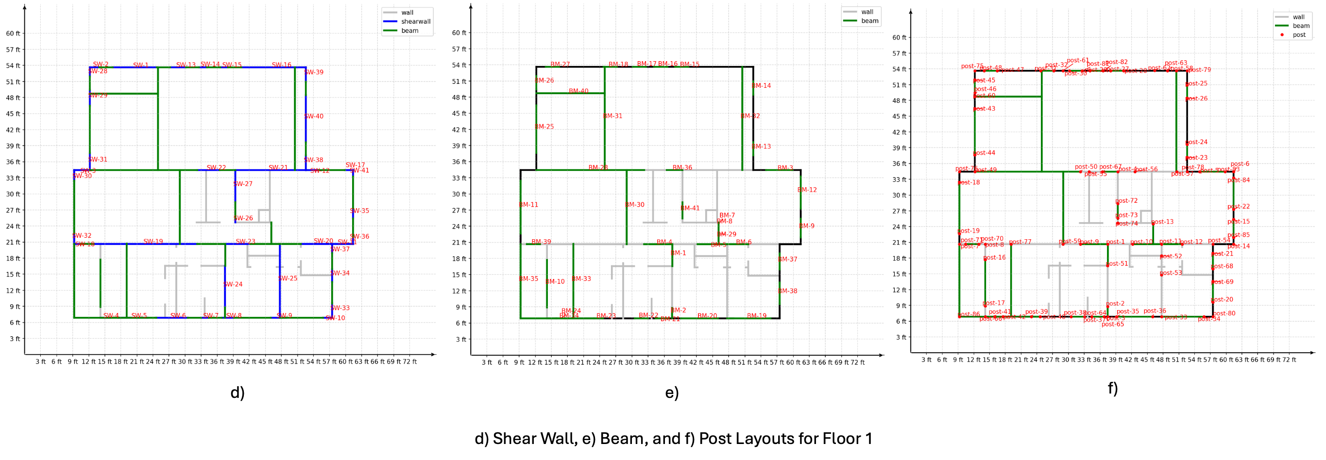
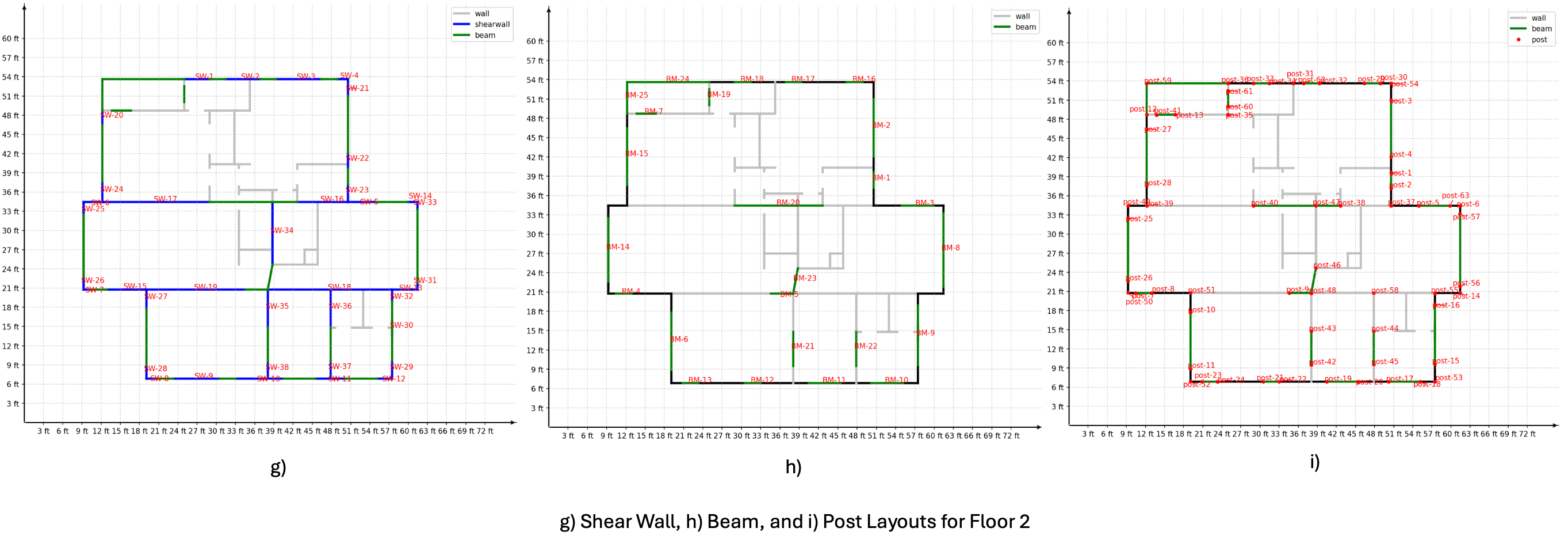
C2. Shear Band, Shear Wall, Beam and Post Layout
The first step to design the lateral system is for our Generative AI to suggest layout options of shear bands. A shear band is similar to a "shear line" or a "braced band" but considers slight offsets between shear walls and beams that form the same shear band.
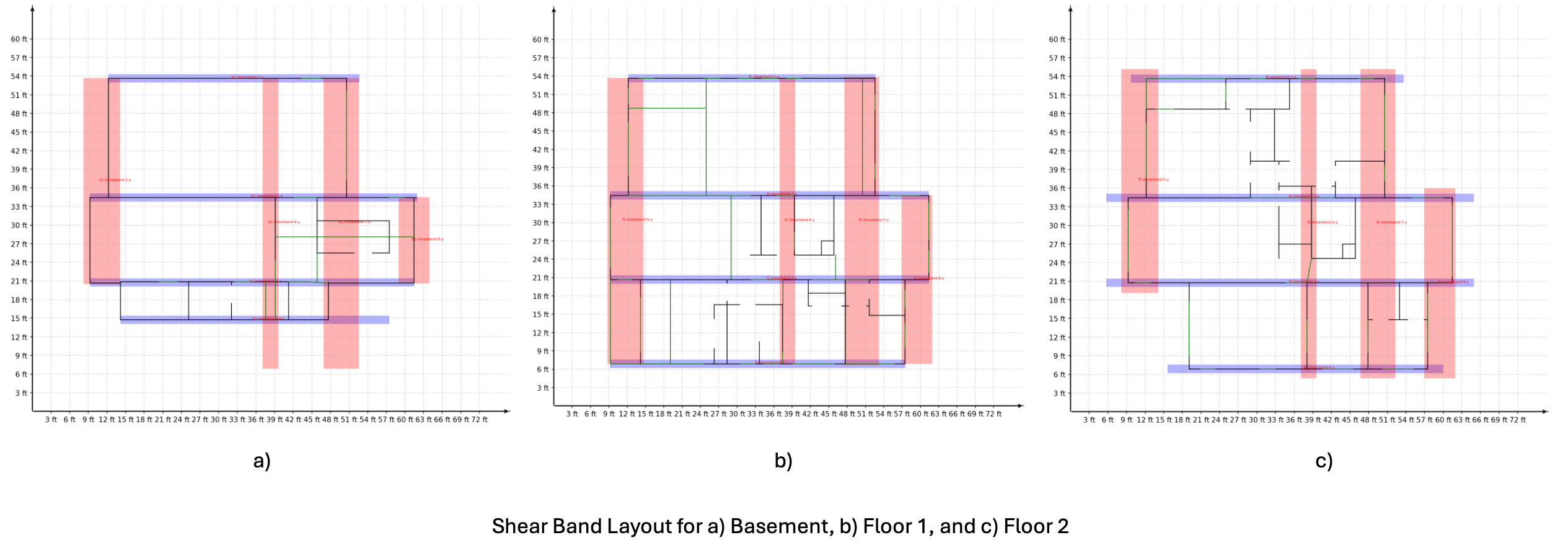
Referencing to these shear band layout, our Generative AI engine therefore proposes layouts of shear walls, beams and posts that actually form these shear bands, as shown in Calculation Sheet.
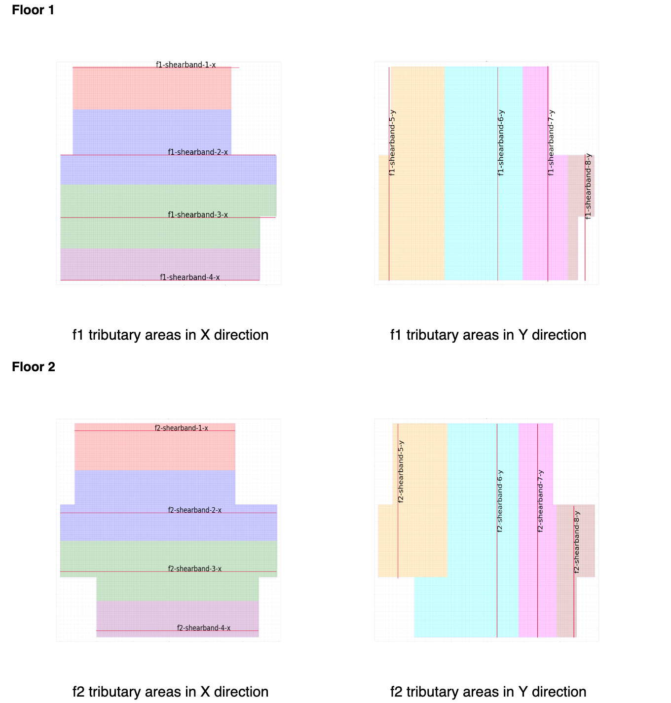
C3. Tributary Area
After the shear bands are established, we establish the tributary areas for each shear band following the "half-half" approach under the flexible diaphragm assumption. These tributary areas are depicted on page 37-38 in Calculation Sheet:
C4. Lateral Forces on Shear Band
In Calculation Sheet, we include summaries of seismic and wind lateral force distributions on each shear band for each floor.
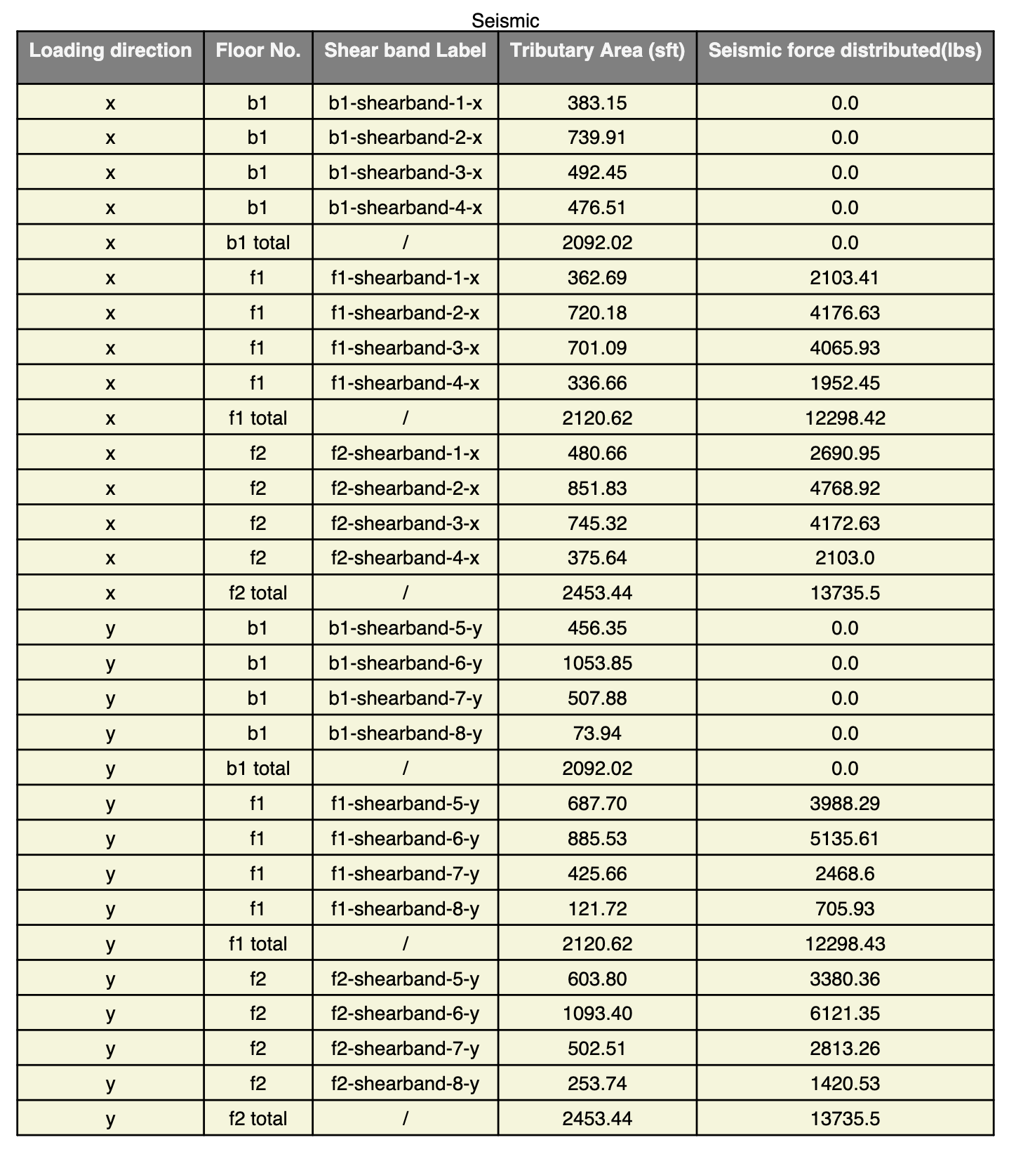
We obtain these numbers by following:
Obtain the seismic and wind load per square foot. For instance, the seismic shear for Floor 2 in x direction is 13855 lbs, and the area of the floor is 2453 sf. Therefore, the seismic load per square foot is 13855 / 2453 = 5.648 psf.
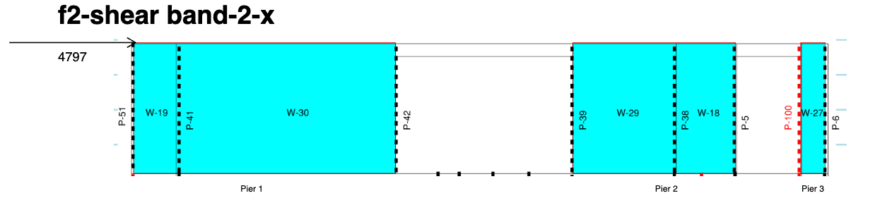
Calculate load by multiplying the tributary area with the load per square foot. For example, the tributary area of "f2-shearband-2-x" is 849 sf, so the seismic force distribute to this shear band is 5.648 × 849 = 4797 lbs.
The same approach is repeated for each shear band across all floors in both x and y directions.
C5. Shear Band Design for Top Floor (without Force Transfer)
As we have now distributed forces to each of the shear band, the last step in designing the LFRS is to design the specific structural components within each shear band.
We follow the segmented approach listed in American Wood Council Special Design Provisions for Wind and Seismic (AWC SDPWS) 2018. To demonstrate how we do it, we will use the same shear band as above "f2-shearband-2-x".
Step 1. Construct the "wall pier"
When we model the architecture, we may chop up walls into segments and label them accordingly to reflect differences between interior and exterior walls. For instance, within "f2-shearband-2-x", wall-29 is an interior wall and wall-18 is an exterior wall. They are labeled as separate walls in our architectural modeling.
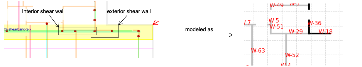
However, when two shear walls are aligned and next to each other, typically they would be sheathed together and work together to resist the lateral forces. Therefore, we introduce the concept of a wall pier, which group these separate walls together to resist the lateral loads. For our example shear band, it will be grouped into three wall piers, and wall-29 and wall-18 are grouped as pier 2.
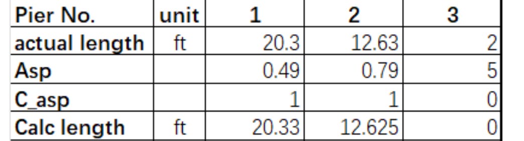
Step 2. Check the calculated length of the pier
According to the AWC SDPWS, the individual wall segment with aspect ratio larger than 3.5 shall not be considered as a shear wall, and a segment with aspect ratio larger than 2 would take shear capacity reduction. The Casp value in the table below is therefore introduced to account for this adjustment. Casp takes value of 0 when the pier's aspect ratio exceeds 3.5 and takes value of 1 when the aspect ratio is less than 2. We then obtain the calculated length of each pier by multiplying Casp with the actual length.
Step 3. Distribute the shear band force into piers
For simplicity and to avoid iterations, we assume the shear capacities of shear walls in the same shear band are the same, so the lateral loads are evenly distributed proportional to each pier's calculated length.
For example, the calculated length of pier 1, 2, and 3 in our example shear band are 20.33', 12.63' and 0', and the total seismic load for this shear band is 4492 lbs. Therefore, the seismic load for pier 2 is 4797 × 12.63 / (20.33 + 12.63 + 0) = 1838 lbs.

Furthermore, the load distributed to each pier is assumed to be resisted by the end posts. For example, the end posts of pier 2 are posts 39 and 5, and each takes half of the load 919 lbs. This load is reflected by the horizontal reactions at the posts' bottoms.
Step 4. Calculate the TC couple on pier ends
The overturning moment of each wall pier equals v × h, where v is the lateral load the pier takes and h is the height of the pier. This overturning moment is resisted by the tension and compression couple occur at pier ends, assuming the studs in the middle do not have any contribution. In addition, the resisting moment of dead loads is not considered, which would yield a more conservative result in our calculations.
The tension and compression couple T = C = v × h / L, where L is the actual length of the pier. For example, for pier 2, the seismic load it takes is 1838 lbs, and the tension and compression on pier ends are 1838 × 10 / 12.63 = 1456 lbs. These loads are reflected by the vertical reactions at the posts' bottoms.

Both the horizontal and vertical reactions form the demands of the end posts.
Step 5. Calculate the shear flow for the pier and determine sheathing
The shear demand for the wall pier equals v/L. For example, for pier 2, the seismic load it takes is 1838 lbs, so the shear for the pier = 1838 / 12.63 = 146 plf.
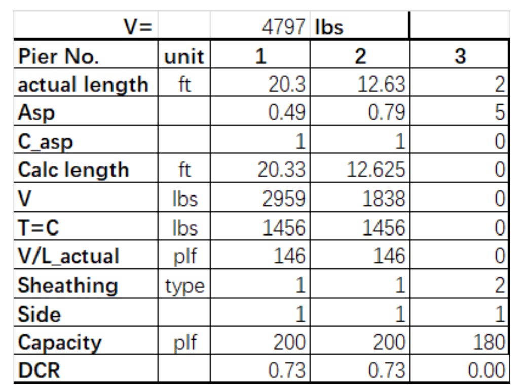
Therefore, the sheathing for the pier, including walls 29 and 18, is designed to be S1_5/16_6d@6, whose capacity is 200 plf. The DCR for these two walls are 0.73. Here, "S1_5/16_6d@6" means
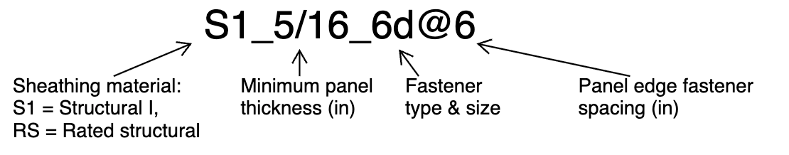
We follow AWC SDPWS Table 4.3A to obtain the shear capacity.
C6. Shear Band Design with Force Transfer
The above section discusses shear band design for the top floor of the building, where we do not need to consider force transfer from the above. When we progress down to other floors, however, we have to consider the impact that the above floor is exerting.
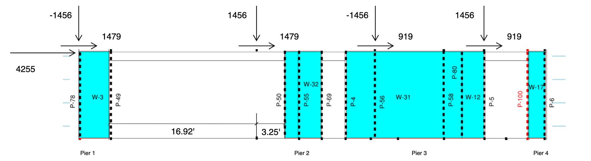
In this case, we will run calculations in the following steps, using "f1-shearband-2-x" as an example:
Step 1. Calculate the total horizontal force
We assume the Rx from the upper posts can be carried to the lower floor through proper connections (e.g. HDU hold-downs or MST straps) and convert the Rx from the upper floor posts into the horizontal loads on the lower floor.
For instance, the Rx for post 51 on Floor 2 is -1479 lbs, and post 51 is located right on post 78 of Floor 1. Therefore, there should be a horizontal force of 1479 lbs on top of post 78 on Floor 1.
The total horizontal force for the shear band equals the sum of all loads from Floor 2 posts and the loads distributed from the tributary area. For shear band "f1-shearband-2-x", the sum of all loads from Floor 2 posts is 1479 + 1479 + 919 + 919 = 4797 lbs and the loads distributed is 4255 lbs. Therefore, the total horizontal force is 9052 lbs.
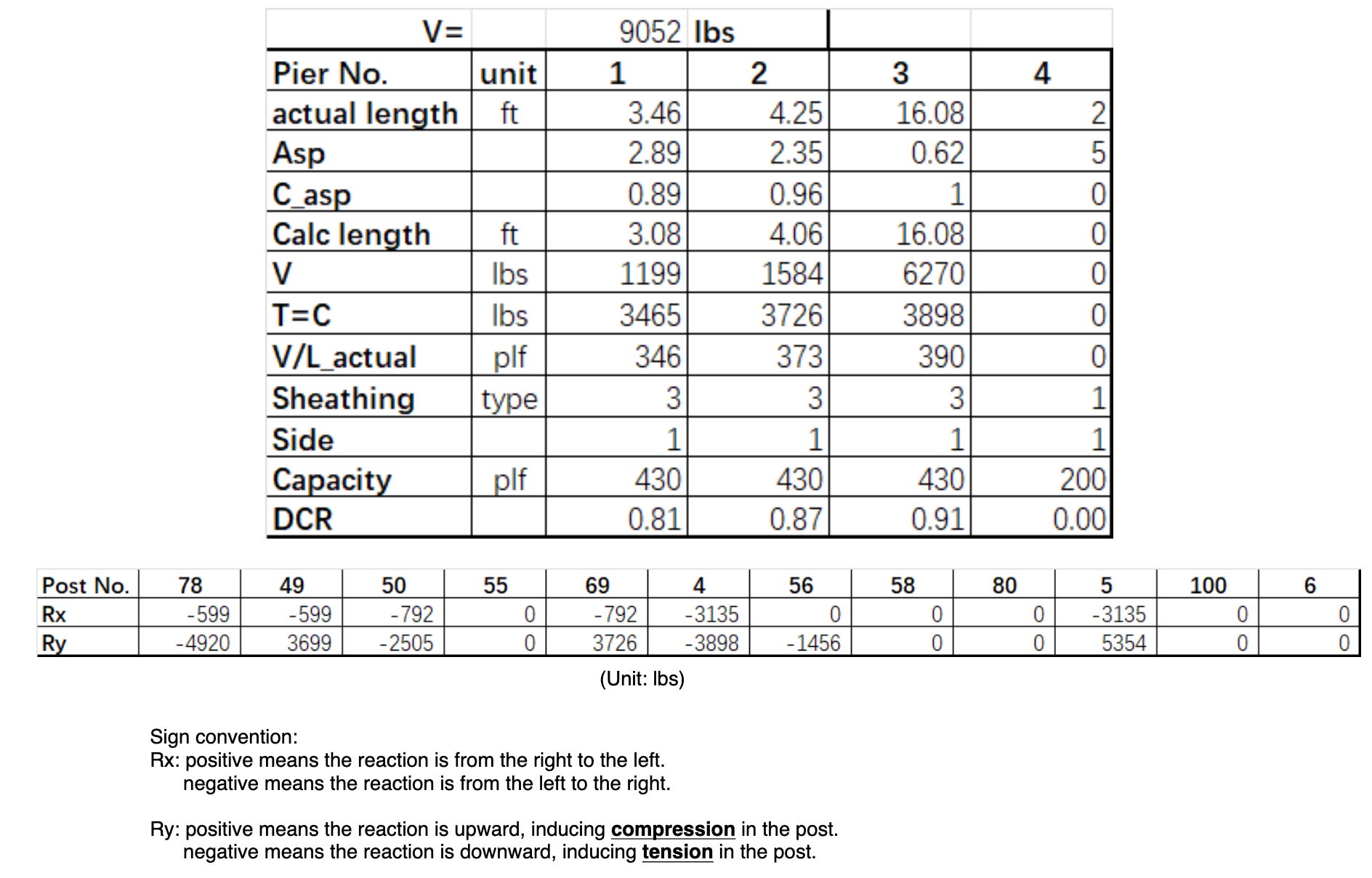
Step 2. Follow the same procedure as mentioned before
As an example, the shear load on pier 4 = 9052 × 16.08 / (3.08 + 4.06 + 16.08 + 0) = 6270 lbs.
Shear demand = 6270 / 160.8 = 390 plf.
Therefore, the sheathing is designed as S1_15/32_8d@4, and the corresponding DCR = 390/430 = 0.91.
The end posts' Ry: T = C = 6270 × 10 / 16.08 = 3898 lbs.
Step 3. Calculate the posts' demands from upper floor
Similar to Step 1, Ry from Floor 2 posts shall be converted into vertical loads on Floor 1. In doing so, there are two scenarios:
The upper floor post sits on a post on the lower floor.
The upper floor post sits on a beam on the lower floor.
For Case 1, the load is assumed to be carried directly by the lower floor post. As an example, post 39 on Floor 2 sits right on post 55 on Floor 1, and Ry for post 39 is -1756 lbs. The load is carried downward to post 55 directly.
For Case 2, the beam is assumed to be simply supported, which means it rests on two supports and is free to move horizontally. Therefore, the load is distributed to the posts on both ends of the beam. For example, post 40 on Floor 2 sits on beam 28 of Floor 1, and loads passed from post 40 onto beam 28 is supported by post 50 of Floor 1: 1456 × 16.95 / (16.92 + 3.25) = 1221 lbs.
Step 4. Calculate the total demand for posts
Add loads from Steps 2 and 3 together to get the total demands for posts.
For instance, the total demand for post 50 on Floor 1 P = -3726 + 1221 = -2505 lbs. The negative value means that the post is in tension under seismic load.
As we demonstrates calculations that derive the lateral system design, in the next article, which will be the last of this series, we will discuss designs for the gravity systems, as well as posts, which are impacted by both lateral and gravity forces.
About the Authors

Robin Li, EIT is the Co-founder and COO of Genia and now leads product management. After graduating from University of British Columbia, Robin started off his career at Arup as a certified structural engineer, where he designed structures for a high-rise casino hotel in Macaw. Later, he returned to Canada and designed 100+ low-rise and mid-rise structures, including high-end custom homes in timber. You can find Robin on Linkedin or email him at robin@genia.design.

Calvin Zheng, EIT joined Genia in 2024 as a product manager. He holds a master’s degree in structural engineering from UCLA and has 5 years of experience designing structures in Los Angeles, first at JCE Structural Engineering Group and later at KPFF.